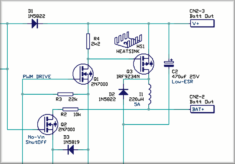
The Circuit Diagram
The electronic design is called a schematic or circuit diagram. It is constructed in CAD format. There are several different PCB CAD packages, however the work follows the same pattern. At AirBorn Electronics it happens we use Protel CAD. Schematic diagrams are constructed according to a number of standards and rules, but the primary function is to explain the circuit design in an easily digestible form. If you are not an electronics person, a circuit may not look that explanatory, or digestible - but it beats all the alternatives.

A circuit diagram is a strict document, and cannot be "mostly correct". (If a diagram shows a simplified representation, it should be called a block diagram, a circuit excerpt, or a representative circuit.) A circuit diagram must reflect the actual construction of the printed circuit board which is made from it, exactly. The printed circuit board CAD and schematic CAD are tied together through a Net-check, and modifications to one document must always be carried out in the other. To Not do this causes confusion and failures, but it does happen, so each diagram carries version numbers and there will be a procedure used to prevent mismatch. The circuit diagram references each part on the printed circuit board with a designator (e.g. "IC5") and pin numbers for each connection.
A good circuit diagram will include extra information required to understand the circuit
operation, have descriptive net and connector labels, and include all of the parts on the
printed circuit board. At AirBorn Electronics our approach is to use "blank" components
for hardware items such as IC sockets, heatsinks, submodules and the PCB laminate itself, so that
 these items appear on the circuit, parts list, and PCB in identical form. We have an (older)
tutorial
on that design method if you want to explore it further.
these items appear on the circuit, parts list, and PCB in identical form. We have an (older)
tutorial
on that design method if you want to explore it further.
A good circuit designer sees the circuit as a whole, ("Holistic approach" is probably the best description.) and doesn't just look at each element of the design in isolation (the "keyhole" approach). While the keyhole approach is a useful simplification applied to the software industry, in the hardware field it will cause you grief. Circuitry affects other circuitry in unanticipated ways, looking at elements in isolation causes you to overlook such interactions. There is no substitute for being thorough.
The design process does work best as an integrated whole. But commercial and workload pressures mean allocation of seperate tasks to subcontractors is the norm rather than the exception. Communication between seperate design teams is covered below. As a company in the past, AirBorn has taken responsibility for specification, circuit, PCB layout, Software, Prototyping, Manufacturing, Testing. We find you can do any one stage, or any sequence of stages, but the only (single) stages we can reliably subcontract to others have been PCB layout or software or manufacturing. Task allocation at other companies may well be different.

Experience counts for a lot in circuit design. Blocks of circuitry get reused. As an example, the small fragment (left) is a circuit that AirBorn often use when an RS485 interface is required. A designer with equivalent experience would have their own equivalent circuit, but a design produced by a newer engineer with only reference to manufacturers data would likely have just one part in their circuit, - they may well use the same 75176 type IC, but in surface mount, taking a tiny 50 square millimetres of PCB space.
The Experienced solution uses a DIP component in an IC socket, (so it's replaceable) and adds an indication LED (to aid diagnosis of cable and peer faults), supply pulling resistors (for better noise immunity), fusible series resistors (to protect against cable mis-wires), and overvoltage clamps (to protect against surges). This solution provides a much better quality circuit. It costs, but experience has taught that it only costs a bit more when you build it - rather than a lot more later, fixing the Problems.
Decisions made during the circuit design also affect the layout - there are small economies to be gained by having the same designer do both of these operations. The designer should specify the physical package to be used in the layout at the time the circuit is designed, rather than leaving this as a seperate task for later. Where Circuit design and PCB layout are not performed by the same person, efficient communication is essential. The authors advice to those managing this process: If there is even a hint of politics between the two parties, it may be best to close it down.
The design of the circuitry also ties in with the programming for the product. When Programmable Logic Devices are being used decisions are made as to which circuitry is inside which devices, and which is external. With the microprocessors, some functions will only work on a subset of the device pins, such as PWM, interrupts or A/D - decisions are made as the circuit is designed that affect how the coding operates. These are basic design decisions that require good communication occur between the Firmware and Hardware people working on your project. It is not really enough that your hardware people generate the header file for the project, - the two teams need to talk. There are always design tradeoffs, and discussing those tradeoffs helps.
 The component package type also affects the circuit design. Smaller Surface mount (SMT / SMD)
parts can dissipate less heat so different values or circuit designs are used.
The component package type also affects the circuit design. Smaller Surface mount (SMT / SMD)
parts can dissipate less heat so different values or circuit designs are used.
There are chips and Modules that make design so much easier, these days. A few years ago the only modules likely to be found in industrial control PCBs were the LCD and the power supply. Now it is possible to use modules for perhaps half the circuitry. Some designers even take out the CPU itself and substitute a pre-built module - that certainly jump starts debugging. The pace of change in the electronics industry has made Researching these parts and modules an important, but rewarding, part of any circuit design. Some good examples are Lithium Ion battery management, Radio communications, USB and ethernet comms, Gyros, compasses - in fact any type of sensor - and increasingly output devices also.
The wealth of modules available today certainly has made it easier for designers to get away without in-depth knowledge of every aspect of their trade. (Because the finer details are already taken care of inside the module) But it becomes important during debugging and when there are problems - low level analog, low power circuitry, robust interface circuitry, Radio circuitry and opto-isolated construction all need a certain amount of expertise.
Hardware, n.: The parts of a computer system that can be kicked.
-- from "Fortunes" ![]()
- Contact Us
- Enquiry Form
- Sitemap
- The PCB design method
- About Circuit diagrams
- About PCB layout
- About Firmware design
- Spec'ing your job
- Our design service
- Example Projects Library
- Mechatronic control unit
- Garbage truck compactor
- RS232-RS485 convert (2006)
- Tone generator test project
- RS485 fire panel int.
- Front panel switches( A/D)
- Serial to IRDA
- Danfoss loop tester
- RAN Multilayer trainer
- Programmable Oscillator
- Pressure sense PCB
- Nursecall overdoor light V2
- Design step-by-step
- Circuit diagrams
- PCB Layout
- PCB Etching
- Prototyping
- Firmware design
- Documentation
- Manufacturing
- Economies of scale
- Test Procedures
- ECOs - changes
- EMI & ESD in design
- FR4 and fire resistance
- Project Specifications
- Specification Intro.
- Writing a Spec
- Tech Ingredients
- Example Specs (older)
- Selecting a designer
- R&D Economics
- Design Inspiration
- Autotrax Utitilities
- Autotrax links
- Our PicoBus IO Std
- RS232 connectors
- Our RS485 converter
- P89LPC932
- Our Program header
- How to use a Multimeter
- Our Site index
- Offsite Links (15000+)
- Google search
- Contact
©2013 AirBorn - Last updated 01 May 2013