
Circuit Diagram
Most of our projects have some pushbutton switches; the most common quantity being one
or four. This board, consequently, gets reinvented over and over for client projects.
Here we have just made a standard version to reuse, and to offer as a quick interim solution.
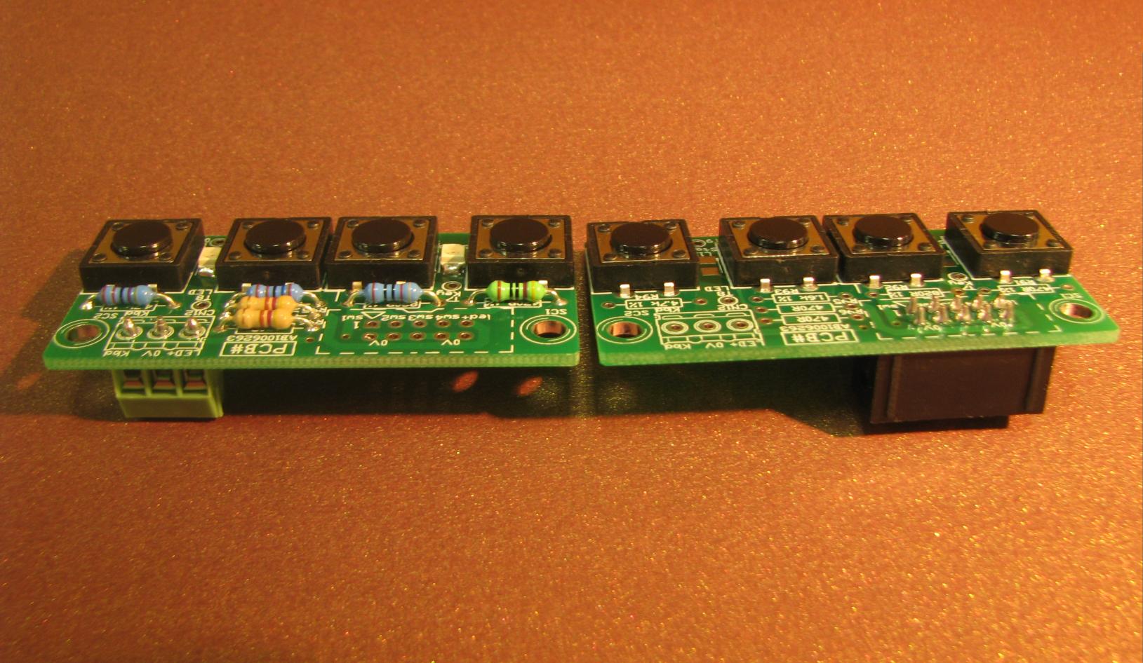
The board comes is used in two versions, one with four individually wired switches - almost
always with the switches being returned to OV or ground. The second is "multiplexed" - to
reduce the number of wires required to connect the keyboard to the main board. There is also
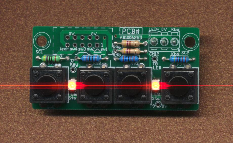
an option to put two surface mount LEDs in the keyboard which can act as illumination or status.
With a larger number of keys, multiplexing normally consists of row scan and column return lines,
with diodes to stop key ghosting. A microprocessor asserts each row scan line in sequence while
monitoring the column return lines for active keys. A 16 switch keyboard multiplexed in this
fashion only requires 8 signals connecting from the microprocessor board to the keyboard,
rather than the 16 signals and return that would be needed for an unmultiplexed keyboard.
However, the traditional method of multiplexing requires 4 signals to multiplex 4 keys - it is no
real improvement on reading the keys directly. The alternative we use here is to "multiplex" the
keys using an analog resistance, converted at the microprocessor into an analog voltage and read
in through an A/D converter. "Multiplexing" is really a misnomer, but conveys the correct idea.
Our "multiplexed" keyboard only requires two wires back to the microprocessor for the 4 keys.
(However, we add a LED signal to the board as well, and so need 3 wires.) At the microprocessor
we have a series resistor of 330R (in order to limit current in the event of a miswire), and then
a pullup resistor of 1.6k to the microprocessor supply rail. For best operation these resistors
should be 1% tolerance type, as should the resistors doing the "multiplexing" on our keyboard.
Given these resistor values, the code for reading the keyboard becomes unbelievably simple.
In Pseudo code the operation is:
| Read value from A/D converter |
| Add (FullRange / 12) to value |
| Integer Divide value by (FullRange / 6) |
| Result 0 = Key 1 pushed |
| Result 1 = Key 2 pushed |
| Result 2 = Key 3 pushed |
| Result 3 = Key 4 pushed |
| Result 4 = No Key pushed |
| Result 5 = No Keyboard connected |
For a 10 bit A/D converter, Full range is 1023, so the divide operation should be using a constant
of 1024/6 = 171. However, only 8 bit resolution is needed - the value for an 8 bit A/D is 43.
This routine also is handy in that it will tell you if the keyboard is unplugged - a nice
diagnostic feature for a type of failure that happens all the time.


