| ||||||||||||||||||||||||||||||||||||||||||||||||||||||||||||||||||||||||||
|
©2010 AirBorn
|
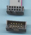
Picobus connector wiringPicobus allows the connection of peripheral components such as switches, LEDs and other Input/Output devices to a microprocessor motherboard - typically an AirIONThe bus is based on a small IDC10 connector, compatible with DIN41651 and MIL-C-83503, without retaining clips. Material is Glass filled polyester, UL94V-0 rated. The cable is 105 degrees rated, UL recognised (generally UL VW-1 flame retardant). All contacts are gold plated.
 The active high multiplex selects, Q0-Q3, are switches
to Vcc that are continuously scanned by the host microprocessor.
Generally, each Mux select is activated for a period of 0.5ms-1ms
in sequence, with each Mux select having an ON duty cycle of 10-25%.
The active high multiplex selects, Q0-Q3, are switches
to Vcc that are continuously scanned by the host microprocessor.
Generally, each Mux select is activated for a period of 0.5ms-1ms
in sequence, with each Mux select having an ON duty cycle of 10-25%.When used in conjunction with the multiplex selects, the two microprocessor port signals DEV,DOD send or receive multiplexed data. For instance, if multiplexing LED indicators, the two Data bits and four Mux selects allow a total of 8 indicators to be attached to one Picobus connector. The DEV and DOD lines may (alternatively) be used as normal unmultiplexed I/O port signals. The AirION implements several Picobus connectors. Each has two dedicated microprocessor port bits: DEV,DOD, - while the remaining Picobus signals are common to all connectors.
Simple LEDs and switches may require no power, and attach between one of the Q0-Q3 lines, and DEV or DOD. More complicated circuits will require power from Gnd and Vcc, and will attach through the i2c bus, and or possibly the port signals. Some circuitry may treat the Q0-Q3 signals as TTL levels, to enable drivers or latches connected to DEV and DOD. The i2c bus is also available to facilitate expansion using that family of devices.
| |||||||||||||||||||||||||||||||||||||||||||||||||||||||||||||||||||||||||