Using a multimeter
This guide starts off with the basics of a meter, proceeds to give a thorough specification for our example meter, then explains how to make measurements, and finishes up with some hints and notes.
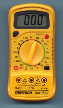
The example meter that we are demonstrating is typical of many economical digital multimeters that you can purchase, this guide will be useful for all these meters. This guide is concentrating on how to use your multimeter. It all came about, frankly, when we started giving away free multimeters to our design clients - and we realised there was no easy instruction manual for a meter - all that was supplied was a list of (sometimes non-sensical) warnings, and a specification list. Admittedly we have a specification list here, but we tell you to ignore it if it does not make sense, and we have reduced the warnings to the three that we think really matter.
We can supply the meter direct - but our costs are a little higher than the big retailers. Recently the same meter has availble only in a dark grey colour case. There is also a cheaper version in a plain rectangular case with no rubber holster - great for students, or a second meter. We charge $9 to mail out these meters within Australia - (email for a quote if you want it sent overseas, but honestly it probably isn't worth it, we get charged about $40+ here in Australia to ship anything internationally).
The Basics
- Powered by 9V battery
- Black probe in COM, Red in VOmA (COM and 10ADC only used for high current)
- Dial measurement required, connect probes to circuit, read value
- DC voltage: 0.2V - 600V in x10 steps
- AC voltage: 200V, 600V ranges only
- DC current: 0.0002A - 0.2A in x10
- DC current (high range): 10A
- Resistance: 200 - 2,000,000ohms in x10 steps
- hfe test (NPN/PNP transistor)
- Continuity buzzer (Except on Aldi ECS820b and some newer models)
- Prices: $99 down to about $20 (OR up to $200 for brand name eg Fluke)
- Where to buy: Online, Jaycar, Dick Smith, Altronics, sometimes Aldi, Bunnings
Warnings
Do not rotate the dial while the meter is connected to a circuit - you may rotate it through a current range, short circuiting the probes and damaging either the meter or the circuit.Respect the circuitry you are working on - If you touch exposed metal, or cause a short circuit, or connect to high voltage, you may expose yourself to hazard - or damage the circuit or your meter.
Measuring the short circuit current of a battery or power supply is usually not safe - it is likely to damage the meter or battery and possibly cause the battery to overheat so much that it may be dangerous.
You should read all the other important warnings in the instructions that come with your meter,
you may even find, somewhere, the author's favourite comical mis-translated warning:
"Do not run the equipment under water or in water shower for fun or any other reason".
![]()
Quick facts for the experts
(Please skip reading this section if it doesn't make sense to you!)- Voltage Measurement: Input impedance 1M
- Current Measurement: Voltage drop 200mV max
- 10A Current Measurement: Voltage drop 100mV
- 20k,200k,2M resistance measurement: 0.35V 22uA (note this means that 20k and above ranges will not falsely read diode drops as resistance)
- 200 ohm, 2k resistance measurement: 2.7V 0.6mA (note this is sufficient to dimly light a good quality Red/Yellow/Green/Orange LED on test)
- AC Voltage Measurement: Averaging only, not RMS (however responds somewhat to change from square to sine, but small 2.0VAC reads as 1.7V)
- Diode test (2k range): Not good, value shown is 2x actual fwd voltage drop
- Hold switch: Holds the last measured value, as you would expect
- Backlight: Illuminates the display for 5 seconds (But is anyone mad enough to try and use the meter on a live circuit in the dark?!)
- Voltage/Current reference: Internal to main AME7106Y IC
- Voltage/Current calibration: Internal 200 ohm cermet preset (VR1)
- Resistance: Resistance measurements are ratiometric
- Battery consumption: 1.57mA typ (But 4.4mA continuity, 40mA backlight)
- Battery life at 1.57mA: Standard 100-150hr typ, Alkaline 200-300hr typ
- Low battery indication: 7V typ, with voltage/current accuracy lost at 6.3V
- Manufacturer: Mastech MAS830L, Full meter schematic
- Transistor test: 9V Vce, 220k base resistor (approx 40ua IBE), 10 Ohm load
- Note 10 Amp current range is Unfused (as in most economical DVMs)
- Current range protection Fuse: 200mA (20mm) no spare provided :-(
- Voltage range protection: Inherent high impedance
- Resistance/continuity range protection: PTC resistor
- Continuity: Standard - buzzer sounds for less than 1500ohm or diode :-(
- Continuity if R29=22k - sounds for less than 100 ohms, but not diodes :-)
- Construction: 'Transistor radio style', Gold flashed PCB switch contacts (Note: Open switch construction - this means keep away from moisture!)
- Active circuitry: LM358, AME7106Y chip-on-board, 1N4007, 4 transistors
- Probes: 18AWG 70cm long, right angle banana, one red, one black
- ECS820b (Aldi meter) Differences from the above
- Continuity setting missing - a pity as very useful
- 2k resistance measurement is 0.3V 22ua
- Diode test is much improved, quite usable
- Backlight is missing, (except for ECS820BL version), probably no great loss
- Battery consumption is improved, 0.93ma (But still 3.76ma on 200R + diode)
- Manufacturer: Was Suns ECS820
- Transistor test: 3V Vce, 180k base resistor (approx 10ua IBE), 40 Ohm load
- Construction : Primarily surface mount, but using nearly identical case moulding
- So all in all there are some technical differences, but aside from the missing continuity feature there is little to tell the meters apart - the rest of the information here can really be read as applying to both the MAS830L / QM1522 or the ECS820B
Measurements for Managers
Just because you have an MBA doesn't mean you have to hire an EE to check a battery voltage! Yep, we have collected all the relevant tricky bits together here, so you can probe and buzz to your hearts content!
As we state above - Have the Black probe in COM, Red probe in VOmA, and dial the measurement you want before you probe the circuit.
Voltage Measurements - DC - definitely the easiest of the lot, Black probe on Ground, Red on the voltage to measure - done. If the value reads negative, the voltage is negative with respect to ground. If the value reads '1.' the voltage is higher than the range setting that you have selected.
Continuity Measurement - definitely the most used setting. Dial the
![]() position, and
put the probes across the two points to be tested, with the circuit unpowered.
The value displayed is the resistance in ohms. If no connection is present, the
value reads '1.' More usefully, the buzzer sounds on low resistance, so that
you can quickly probe for continuity without looking over at the meter each time.
(This feature is missing on the ECS820B)
position, and
put the probes across the two points to be tested, with the circuit unpowered.
The value displayed is the resistance in ohms. If no connection is present, the
value reads '1.' More usefully, the buzzer sounds on low resistance, so that
you can quickly probe for continuity without looking over at the meter each time.
(This feature is missing on the ECS820B)
![[Graphic: PCB]](../method/stargnd.jpg) Resistance Measurement - as for continuity, again, '1.' means no connection
or a resistance larger than the range setting that you have selected.
Resistance Measurement - as for continuity, again, '1.' means no connection
or a resistance larger than the range setting that you have selected.
Voltage Measurement - AC - as for DC voltage, however AC voltage does not have a distinct polarity. Be very careful when measuring high voltages. Just because you are holding a meter does not mean you are now immune to electric shock. Exercise caution.
Current Measurement - DC - to measure the current flowing through a circuit you must insert the meter in series with the circuit. This means you must disconnect a wire, and insert the meter in its place. Normally you would connect the Red VOmA probe in the positive direction, and the Black COM probe in the negative direction. Remove the power from the circuit before doing this. When you have the wires secure and are sure they will not drop off and short circuit, reattach the power. If the value reads negative, the current flow is negative (that is, the VOmA probe has been connected in the more negative direction). If the value reads '1.' the current is higher than the range setting that you have selected. For currents higher than 0.2A use the 10A range.
Current Measurement - 10A DC - as for Current Measurement DC, but using the COM and 10ADC terminals. Exercise caution - the 10A DC range is unfused, if the current exceeds 10A damage to the meter will result. Make the measurement quickly - the connecting leads will get warm at 10A current!
The first rule of intelligent tinkering is to save all the parts
-- Paul Ralph Erlich
![]()
Real world Measurements
hfe Measurement - Insert the transistor in the test socket with the leads matching the E C B postions. The display will show the approximate gain of the transistor. This function is, frankly, pretty rarely used.
Diode Measurement - On the MAS830L Select the 2k (Or, the
![]() position).
On the ECS820B use the setting marked with the diode symbol. Connect the Red VOmA lead
to the anode (unmarked) end of the diode, and the Black COM lead to the cathode
(Bar or stripe marked) end of the diode. If the diode is good, a value
representing the forward voltage drop in millivolts will be displayed.
position).
On the ECS820B use the setting marked with the diode symbol. Connect the Red VOmA lead
to the anode (unmarked) end of the diode, and the Black COM lead to the cathode
(Bar or stripe marked) end of the diode. If the diode is good, a value
representing the forward voltage drop in millivolts will be displayed.
The ECS820B does a good job of this, the MAS830L is not very good at it, as R12 PTC is not well selected for the design. MAS830 value displayed is approx 2x the actual voltage drop of the diode. In any case, diodes rarely fail by exhibiting a higher forward voltage than they should, they most usually fail by going close to short circuit. Even though the measured value is very inaccurate, the meter is still okay for such a Go / No-Go diode test.
LEDs - Red VOmA probe to anode or longer lead, Black COM probe to cathode or flat-marked side of package. On 200ohm and continuity settings 0.7ma flows through a Red/Green/Yellow/Orange LED - just enough to dimly light a good quality LED. White and blue LEDs generally will not light - they require more than the 2.7V or so supplied by the meter.
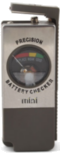 As tersely explained to the left, a battery can be tested, seperately,
using a multimeter - but is best tested (supplying power) in the equipment.
This is difficult for most people.
As tersely explained to the left, a battery can be tested, seperately,
using a multimeter - but is best tested (supplying power) in the equipment.
This is difficult for most people.An alternative is to buy a purpose built battery tester: This is just a meter with a resistor to draw power from the battery, so it is tested under load, as it should be. A simple cheap battery tester is here
(For Theresa Hackett - thank you for your help)
1.5V Batteries - A Fresh battery reads 1.56V, A battery is perhaps half used at 1.35V, and is pretty dead by the time it reaches 1.1V. (Matching figures for 9V: Full = 9.36V, Half = 8.1V, Dead = 6.6V). However, not every item is the same, and some equipment needs a battery with low internal impedance. The amount of current a battery can deliver is not reliably reflected by its open circuit terminal voltage. The best way to check, if in doubt, is to measure battery voltage while the equipment is running.
Lead acid batteries - A 12V lead acid battery generally measures 13.4 to 14V while on charge. When off charge, a full battery will be up at about 12.8V, a discharged battery at about 11V. If a lead acid battery is in the range of 6-8V it is probably in pretty bad shape, and over discharged, or with a shorted cell. A shorted cell makes a 12V battery pretty much useless.
Lithium Ion batteries - Lithium Ion batteries are the newer type of rechargeable battery. When fully charged the voltage rises to 4.2V, and at the end of charge the voltage falls to 3.0V - or sometimes down to 2.7V depending on the product. However, these batteries need to be treated with caution. Use only the proper charger, do not short circuit, and do not open them - Lithium incinerates on contact with water. If allowed to completely discharge these batteries are irreversibly damaged. Despite what manufacturers may tell you, these batteries are like any other - they will last 500-1000 charge/discharge cycles if treated well, and that is all - then they need replacement.
The older type of rechargeable battery is Nickel Metal Hydride (NiMh) and Nickel Cadmium (NiCd). These cells are often the same physical size as 1.5V batteries, but a slightly lower voltage: 1.25V when charged, 0.9V when discharged. These batteries are about twice the weight of LiIons for the same capacity. NiCd and NiMh batteries tend to self-discharge over time, sometimes lasting only a few weeks between charges, whether or not they are used. A good example being older NiCd cordless drills - they always seemed to have a discharged battery when you really need them! You cannot easily replace NiCd batteries with LiIon as they are different voltages - you need to replace the whole product, and in cordless drills the batteries are not accessible in any case. There are LSD (Low Self Discharge) NiMh and NiCd batteries available that largely alleviate this problem, the leading brand is Sanyo Eneloop.
Elements/Heaters - The resistance of a heater can be calculated by first
finding its rated current, and then finding its resistance using ohms law.
The heaters current is:
Power / Voltage = Current
e.g. A 1200W 240V heater uses 5 Amps.
Then the heaters resistance is:
Voltage / Current = Resistance
e.g. A 240V 5A heater is 48 ohms.
Knowing an expected resistance, if the heater was measured and found to
be wildly different from these values, you would guess that it was faulty.
However, the ohms law calculations are not useful for halogen lights or
transformers. The 'cold' resistance of a light bulb is frequently as little as
a tenth of its running resistance - so a 500W 240V halogen light bulb,
which you would calculate to have a resistance of about 120 ohms, actually
has a 'cold' resistance that measures closer to 12 ohms.
Power supplies - please note our warning at the start of this document - it is usually quite dangerous to measure the short circuit current of a battery or power supply - don't try it! If a power supply is unregulated, frequently the output voltage will be up to a third higher than its rated voltage when there is no load connected. '12V' regulated supplies for equipment that would normally be battery operated are usually 13.4 - 13.8V, not really 12V at all! Power supplies for digital logic are normally regulated to +/-5% or better, so you would expect a 5V power supply to be 4.75 to 5.25V without exception.
![[Graphic: PCB]](../method/pcbfrag2.jpg) Components in circuit - Normally you have to remove a component from
a circuit in order to reliably measure its value. For instance, if a 400 ohm relay coil
had a 1N4002 diode across it, it would be quite difficult to reliably measure either
the resistance of the relay coil, or the foward voltage of the diode - any measurement
of one is likely to have the other components interfere with the reading.
Almost all circuits are like this to some degree. Most components cannot be measured
in circuit. The only thing that can be reliably be said is that you will not measure a
resistance greater than a resistor value - the circuit can only lower the resistance reading.
Contacts, because they generally read as a dead short: '0.0' are not much affected by
being in circuit. To some extent it is safe to test contacts in circuit.
Ofcourse there has to be an exception: If there are two or more
contacts in parallel, and they read as continuous, you know that atleast one is closed
but you cannot be sure which (if any) of them is open.
Components in circuit - Normally you have to remove a component from
a circuit in order to reliably measure its value. For instance, if a 400 ohm relay coil
had a 1N4002 diode across it, it would be quite difficult to reliably measure either
the resistance of the relay coil, or the foward voltage of the diode - any measurement
of one is likely to have the other components interfere with the reading.
Almost all circuits are like this to some degree. Most components cannot be measured
in circuit. The only thing that can be reliably be said is that you will not measure a
resistance greater than a resistor value - the circuit can only lower the resistance reading.
Contacts, because they generally read as a dead short: '0.0' are not much affected by
being in circuit. To some extent it is safe to test contacts in circuit.
Ofcourse there has to be an exception: If there are two or more
contacts in parallel, and they read as continuous, you know that atleast one is closed
but you cannot be sure which (if any) of them is open.
Fast changes - If a measurement is not stable for a second or so, it is difficult to get a reliable reading with a meter. An oscilloscope is needed for this.
Cables - Cables are easily tested with a meter on continuity setting. Usually cable faults will either be an open circuit or short circuit. It is a rare though possible fault to have a conductor show a significant resistance. Most often, the continuity test on a meter is used to check if the cable pins are going to the expected place on a connector, by buzzing each circuit in turn.
Voltage drop - A meter is the ideal tool for diagnosing voltage drop. Generally, cabling should not drop a significant portion of supply voltage. If a nominal 12V power supply is feeding a device through a long cable, with say 13.6V at the power supply, you would expect to still have atleast 90% of the power (or 12.2V) available at the powered device.
Low voltage - Teamed up with Voltage drop is the droop in supply voltage that can occur when a power supply is overloaded. Again, if a power supply is significantly lower than the expected value (90% is a good starting point) then it is likely that the load is drawing too much current. The only way to find this out is to use a meter.
Monitored circuits - Most alarm systems use monitored circuits - basically contacts in series and parallel with resistors. While two wires may come back to the alarm panel, instead of being just a closed circuit or open circuit to indicate the condition, the wires will have two values of resistance for the two states. During installation, this is easily checked with a meter on resistance setting, but it relies on disconnecting the wires from the panel first so that the panel circuitry does not interfere with the measured value.
Transistor test - The hfe test on a multimeter is rarely used. However, each bipolar transistor has the circuit equivalent of two diodes within it, and testing these is often done. The common terminal of the two diodes is the base of the transistor - for an NPN transistor, the two anodes are at the base. For a PNP transistor the two cathodes are at the base. Many transistor failures will be accomanied by one or both of the diode equivalents within the transistor failing.
Jumper leads / Crocodile clips / Test leads - Called different names in different places, basically a 30cm length of insulated wire with a clip on each end. Two (or more) of these make connecting a meter into a circuit a lot easier.
Low battery voltage in a multimeter - The low battery indication in the example multimeter comes on when the battery voltage falls below 7V. It pays to replace the battery quickly. If the voltage falls below (about) 6.3V, then voltage and current measurements are no longer accurate. Typically, the meter will indicate that the voltage or current is higher than it is in reality. Interestingly, resistance measurements stay accurate to far lower supply voltages, as the resistance measurements are made ratiometrically and so compensate for the lowered battery voltage in the meter.
Autoranging meters - Many multimeters are available with autoranging functions. Instead of selecting the required voltage range, just DC voltage is selected, and the meter selects the best range itself. Also meters are available that will connect to a PC to download readings, or with functions such as capacitance, inductance and frequency measurement, all of which are quite useful. There is also temperature, light, sound level and humidity measurement - really the sky is the limit if you want to get a meter with extra features! Multimeters are sometimes also referred to as DVMs, multitesters, or that-thing-in-the-toolbox-that-I-don't-know-how-to-use
A second meter - Perhaps the most useful hint of the lot is to have a second meter. I personally swear by it - I am constantly measuring voltage and current at the same time, or using one meter for buzzing out a circuit board when the power is off, while the other is set up to monitor voltages in the same board when the power gets turned on.
- Contact Us
- Enquiry Form
- Sitemap
- The PCB design method
- About Circuit diagrams
- About PCB layout
- About Firmware design
- Spec'ing your job
- Our design service
- Example Projects Library
- Mechatronic control unit
- Garbage truck compactor
- RS232-RS485 convert (2006)
- Tone generator test project
- RS485 fire panel int.
- Front panel switches( A/D)
- Serial to IRDA
- Danfoss loop tester
- RAN Multilayer trainer
- Programmable Oscillator
- Pressure sense PCB
- Nursecall overdoor light V2
- Design step-by-step
- Circuit diagrams
- PCB Layout
- PCB Etching
- Prototyping
- Firmware design
- Documentation
- Manufacturing
- Economies of scale
- Test Procedures
- ECOs - changes
- EMI & ESD in design
- FR4 and fire resistance
- Project Specifications
- Specification Intro.
- Writing a Spec
- Tech Ingredients
- Example Specs (older)
- Selecting a designer
- R&D Economics
- Design Inspiration
- Autotrax Utitilities
- Autotrax links
- Our PicoBus IO Std
- RS232 connectors
- Our RS485 converter
- P89LPC932
- Our Program header
- How to use a Multimeter
- Our Site index
- Offsite Links (15000+)
- Google search
- Contact
©2013 AirBorn - Last updated 01 May 2013