PROTEL Autotrax - known issues, and unobvious solutions
Ever spoken to someone about a software package they use every day, and been surprised to find that they never, ever, have any problems with it? Never lose a file, never get an unintended result? Sometimes it is just a matter of knowing what NOT to do!
You must size strings in multiples of 12 thou, if you don't they will display as if they WERE multiples of 12 thou, until you come to manufacture, where they may change.
The hole sizes in all the protel PCB libraries are not really correct. They are often odd values like "23 thou". I believe that what was intended was that a designer could layout their board, and AT THE END decide that they wanted, for instance, to use no IC sockets, so 28 thou was the best size, or IC sockets, so 32 thou was the best size - and then they could do a global hole size edit of just hole sizes matching "23 thou" to these new, real, sizes. Actually, a far better technique is to make them all 32 thou and be done with it, as often this last step get reliably missed in the rush to get prototypes made! Check all your hole sizes.
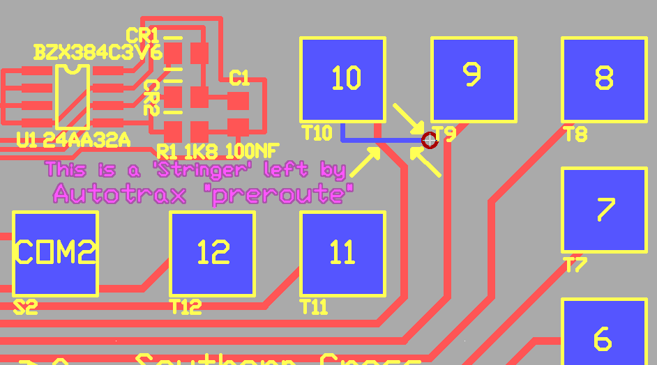
You should not select autoroute "pre-route" while you have SMT pads on the board - it will sometimes add little PTH via pads beside the SMT ("stringers") even if they don't need them, and even if they short to neighbouring pads. Well, actually, once you know where these "stringers" will be dropped, and what to look for, you will find pre-route is still very useful. Autotrax does not seem to place them on all Surface mount pads, and stops placing them once those particular surface mount pads have been connected using tracks and the route is removed from the netlist.
In Autotrax, SMT pads will only be produced without a hole if the hole size is set to 0. Be careful that you specify a hole size of 0 for SMT pads
Octagonal pads are rotated by 22.5 degrees in gerber plots. Most australian manufacturers then rotate them back again for you. The author elects not to use octagonal pads for this reason, unless generating the gerbers as well. This issue may be duplicated in other versions of Protel software.
Protel Autotrax was originally a DOS package. It uses 8.3 filenames, so you must should limit the file name to (7 or) 8 characters with ".PCB" at the end. If you use long filenames, for instance "controller.pcb" then your operating system will make the filename accessible as "contro~1.pcb" or, if similar long file names already exist, perhaps "contro~2.pcb" etc. This will cause you difficulties in the longer term, limit yourself to seven characters, for instance "control.pcb" and then when you need a new version you can call it "control2.pcb"
While Protel Autotrax was originally a DOS package, it is not correct to say it is command line driven. If you set up Autotrax the normal way in DOSBox you will never see a command line - all operations happen in a GUI.
DOSBox allows Autotrax PCB (Traxedit) to run full screen - but only on the primary monitor (#1). The authors of DOSBox are just a little touchy on some subjects, and say this is a limitation of SDL, the base library. This is partly true, the older version of SDL that they use is limited in this respect. If you want to use Autotrax in 1280 x 1024 and set up your 1280 x 1024 monitor as monitor 1, using the package full screen will be easy. The DOSBox authors also insist that their package "is intended primarily for games" which seems rather ab arbitary limitation to impose upon their audience. But hey, they source is open and no one gets charged for the app!
Sometimes when rotating components with rectangular SMT pads on PCBs - or perhaps when you rotate block selected areas, the author is not completely sure - you will get the X and Y values for the pads swopped. That is, everything will rotate by 90 degrees, but if the longest dimension of the pad was horizontal it will still be horizontal. This is usually immediately obvious. It is not random - it happens when you do something unusual first (The author has not been able to pin down what this is - as it very rarely happens to him! Perhaps it happens when the pads are not part of a component, but are "exploded" or primitives - email me if you know what causes this!)
The "netlist:length" command in PCB does not seem to yield a useful measurement
The PCB design rule check is pretty reliable - but reading the report takes some experience - it tells you that there is a fault, but often twice, and often in a way you are not expecting. (For instance if you reverse the ground and VCC connections on an IC, you may get hundreds of reported errors on a large PCB, when there is only, really, two.) The author finds it particularly useful on a dual monitor system to have schematic running on one monitor, PCB on the other, and to open PCBname.drc in a text viewer window over one side of the schematic.
DRC sometimes shows an error for strings in copper when there is not one - be careful though - some manufacturers somehow screw up translation of copper stings - I have had shorts. I tend to leave a bit of extra room around copper strings now.
If you have two pads with the same pin number in a component (which happens with some tactile switches) then PCB DRC will throw up a lot of errors, - especially if you then use the tactile switch as a jumper. The only solution is to show the four pins on the schematic - or make a PCB library component with two pins and two soldered unnumbered pads.
When producing a multilayer board, Vias cannot be connected to the Ground plane or VCC plane. The solution is to use individual pads as vias, as any pad can be individually edited to connect to the ground plane or VCC plane as required. See manual P43. However, be very careful with any translation of the final multilayer PCB file to other formats - while Protel V2.8 generally handles the translation correctly, other Protel versions may lose the plane connection information saved in an Autotrax file, although the outside layers of the PCB will seem to be correct. Have any translation done by someone who knows what they are doing!
The Autorouter included in Autotrax is not really very good. You are much better off manually placing tracks. I find the autorouter most useful as a yardstick test after I finish placement, before I begin manual routing. (Remember to do this on a COPY of your work!) If the autorouter can achieve 95% routing, I know the board will be a very easy manual route job. If the autorouter can achieve 85%-90% routing, I know the board will be a moderate manual route job. Also, using the autorouter to process just preroutes cleans up the "rubber band rats nest" that is used to guide placement during manual routing.
Autotrax works in units of 1 thouandth of an inch internally. When you set the package to metric, it does the best job it can at conversion - but it is converting every step of the way. You are better off working in inches, you will have more control. 1 thousandth of an inch is 0.0254mm - and in making the pad spacing for a new libary component, for instance - the error can cumulatively add up to a significant amount if reapplied over the length of the side of a QFP. It is best to work in the native resolution of the package.
Generally Autotrax is pretty well behaved - it doesn't seem to trash files, lock up, or crash. And, it is 20+ years old, so one would think we would already have seen any problems that were going to occur.
Issues for Schematic
Protel Autotrax V1.61ND was the last version sold - and was previously available free on Protels website. When sold, it was accompanied by Schematic: Schedit.exe V3.31
If you overlap a line and a pin in schematic (instead of joining them exactly end to end) then a connection will not be made. Helpfully, however, POST will show the line segment as an error. You get used to this - and it is actually part of the way the package operates - its a side-effect, not a bug as such, - the package has no real way of determining your intentions if you do not explicitly connect point-to-point - you may have intended to cross over the pin and connect to another line, for instance (seems ridiculous, but it is possible).
Sometimes you can manage to save highlighted tracks in Schematic. Not really a bug - but it does surprise you when you next open the circuit.
If you make very large multipart components in schematic, you will chew through the available memory very quickly. One such component that is tempting is an mutlipart DE9/DB25 RS232 connector, where you can place the individual pins one at a time, and the program automatically knows the signal name. A few of these and you will run out of memory. The standard connector pins that schematic provides need the pin name entered every time, but they use virtually no memory. Another tempting one is a SIP resistor with several resistors to a common.
Issues for Schematic Libmake
Libmake is a dodgy program, it tends to crash. Be very methodical when editing schematic libraries, make regular backups. Open a library, edit or create a part, back out, save and quit. Then do the next part, - backup between if you are really cautious. Libmake seems to work fine if you follow this pattern. But when you do a whole session, editing a lot of parts without saving, then it often seems that Libmake crashes just before you finish :-(
Issues for Plot
Traxplot generates a ZERO relief around vias for multilayer boards with power and ground planes. This will make every via a short between power and ground, and so make the boards quite unusable. The solution is to run DCode32 and Grounder32 with the Pads and Vias option (see Richard Astons Utilities) on every multilayer board before using Traxplot to make artwork. Or use another package to generate gerbers, atleast for multilayer.
This program will seem to run more slowly if its window is not "maximized". Also, because it expects to print directly to the printer hardware, some new types of printers will not operate. Generally, HPLSR300 is a good type of printer format that will certainly still work with just about all HP printers (and others - the brother HL1240 for instance). Otherwise you can either track down an early protel windows demo version and use that to print your autotrax artwork (a lot of effort, really), or use postscript and ghostview (for very good results, but an investment in installation) or use Matthais Hartl's PCX drivers.
PCB to DXF
The utility called PCBTODXF.EXE allows you to generate a DXF file from an Autotrax PCB. While it is an older 16 bit exe and the dxf format that it generates is also very old, it does allow you to translate your PCB file across in a universally importable format. Just be sure to give your recipeients some idea of scale as I have had people questioning if a board is 3 x 4 millimeters - when actually the PCB was 3 x 4 inches...
Some small utilties come with Autotrax, in the archive UTILARC.EXE. They are all 16 bit .exe's, so they all have to run under DOSBox. There are two translators to import earlier versions of Protel PCB into Autotrax (PCB3CON and PLIB3CON), a tranlator that can import an early PADs PCB format to Autotrax, a basic BOM generator, and a basic Net importer. See the protel autotrax manual for details.
Protel Autotrax Workarounds
...How to do things that weren't thought of originally...
Non-Plated-Thru-Holes. The accepted method for putting a non-plated hole on a board is to make the hole diameter larger than the pad. For instance, 3.5mm holes are often used corner mounting for a small PCB. 3.5mm is 138thou, so the hole size is made 138, and then pad size is made 136. Autotrax supports this. What Autotrax does not directly support is a hole size of 138thou and a pad size of 0 or 1 thou - but if you edit a component manually, Autotrax will faithfully save, copy, and resuse the pad showing no copper at all on the layout - which matches reality. Non-plated-thru holes are usually used where mechanical tolerance is quite important. The plating on the inside of a hole can make its size vary by a few thousandth of an inch - whereas a well drilled non plated hole is accurate.
Small Lettering. Autotrax string sizes jump in units of 12 thou, and the smallest Lettering that can usually be selected is 36 thou (0.91mm). This size of lettering was quite okay on older conventional boards, but 24 thou is more useful for surface mount PCBs. While you cannot select 24 thou lettering in the Autotrax package, if you manually edit a copy of "traxedit.dft" and then paste it into your PCB directory each time you do Surface mount, Autotrax will pick up the 24 thou string sizes and reliably put lettering on your board at that size. 12 thou works as well, if it comes to that, but at 12 thou lettering is getting beyond the capabilities of most PCB silkscreening. (Although some manufacturers use photoimageable component legend, and that often CAN show 12 thou)
Tented Vias. Autotrax does not actually generate a soldermask layer. The soldermask is generated by other tools. Generally the PCB manufacturer will generate a soldermask from a Pad layer by applying an expansion (2 mil or so) to the pads. They can choose to exclude vias from the Pad list used to generate the soldermask - this gives you tented vias. Gerber tools can have the same functionality. This leads on to Soldermask free copper areas - these can be constructed from surface mount pads. For instance, it may be desireable to have a heavy power supply track free of copper so that it can pick up an extra layer of solder during a wave soldering process, and thus be able to be overrated.
Rotated components. Sometimes it is desirable to rotate components so that they fit the layout better - for instance a microswitch may need to be mounted at a correct angle to intercept a mechanical lever. There is a utility called Twist32 by Richard Aston that really simplifies this task. It takes a PCB and rotates the whole thing by an arbitary angle. Because of the Autotrax format, it cannot really rotate partial Arcs or fills - so there may be a little manual cleanup required, but this utiltity is a real time saver. If there were lots of rotated components, and there were lots of partial arcs or fills, it may otherwise be better to find another PCB CAD package to do the job.
Mechanical Layer. Usually the bottom overlay ends up being used as a mechanical layer - to show dimensions, cutouts, and other mechanical features. It is useful because all the tools support that layer, and it carries through on all the diagrams.
Buried vias. I don't know of an accepted way to do buried vias using Autotrax. I would imagine that it would be possible to indicate buried vias by using Surface Mount Pads on inner layers with a hole size equal to the via size. Gerber or other manufacturing software could then interprete the file, deduce that the holes were on inner layers and construct the correct drill files to make buried vias - but I have not seen this done. I would suggest that buried vias may be a step too far for Autotrax, and newer, better, tools might be required for that task.
Libary Limit The Autotrax library is limited to 200 components. I guess back pre-1990's this seemed quite a few - remembering back then that most components were DIP, and only a few surface mount variants were about. Nowadays it is positively limiting. The answer for me has been to have one main library with the most useful parts, and other libraries with less used parts in a hierachical order. It is usually necessary to swop in and out of 3 libraries when I design a board - but that mostly happens just once when I do the "autoplace" (= dump) of all the components from the schematic netlist onto the new PCB outline. See manual P262.
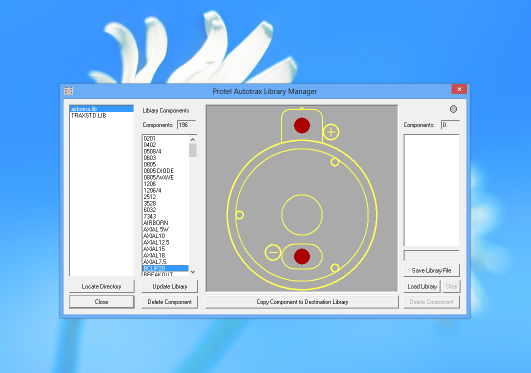
Substantial assistance in managing libraries is prvoided by Richard Astons Library Wizard which can view and copy Autotrax library components between libraries, a lot less tedious than cutting and pasting in Autotrax itself.
Adding components to a Protel Autotrax library is not completely obvious to a new user. For a tutorial, see manual P48. While a board can be made of any number of components, components themselves are only made of primitives - Pads, tracks, arcs, strings, fills. If you want to modify a component, place it out of the way and use command "LE" (Library Explode) to convert it to primitives before you modify it. Every component must have some drawing of some sort on the overlay (legend/silkscreen) layer. Once you have made your new component, you need to use "BD" (Block Define) to select the area before using "LA" (Library Add) to put the component in your library. For ease of use, try and select the exact center of the component when doing the Block Define - that point is the X,Y location of the component from then on - having it as the center of your part will help you a great deal in placement later (because rotate works), and possibly also in Surface Mount programming, because the XY coordinates are likely to be the component centroid.
Rubber banding Autotrax correctly shows Netlist connections as rubber bands (in grey/white) using the "NSA" command after a netlist has been loaded. However, all the rubber bands are the same colour, and PCBs being the way they are frequently the rubber bands overlay so you cannot easily see what connects where. The workaround is to pick up a component ("MC" command) and move it back and forth - the rubber bands will follow, and distinction between nets will be much easier - then use the "Esc" key to drop the component back where it was originally, so that you do not mess up your placement.
Protel File Format The protel file format is documented to some degree in AUTOTFAQ.TXT The description that is given is more an example with notes than an actual description. In contrast the netlist format is described in that document quite completely.
RS274-X Gerbers TraxPlot, the printer driver that comes with Autotrax produces Gerbers that are quite an old format. The preferred format of Gerber is RS274-X. You need to either send the native Autotrax PCB file to a manufacturer to have a board made, or have the Gerber produced by a third party tool. We offer a service converting Autotrax PCB files to RS274-X gerbers. Some people use a later copy of Protel (particularly PFW 2.8) for importing Autotrax and making RS274-X Gerber files.
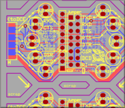
Panelizing. This is not really a workaround, but is mentioned here for completeness. When making up a panel of several PCBs for production, read in each PCB using the Block Read command, which reads in a seperate PCB file as a new block to place on the current PCB. Do not try and use Block Copy as that is intended to be used for duplicating identical areas of circuitry on the same PCB - when using Block Copy Autotrax creates a whole new set of Designators: So if the first area of circuitry had IC1,2,3 & 4 on it, the second copied area will be labelled IC5,6,7 & 8. That is not what you want when you are panellising PCBs.
Route to Outline. This is not really a workaround either, but a method of operation. The standard way of indicating a PCB border in Autotrax is a track on the Keep-Out layer. The center of the track indicates the edge of the PCB - so the width of the track is really not that important. Usually a track of 8 or 12 thou is used. For complex routing, the track dictates how the board will be routed. Routed slots or complex internal routes are also usually indicated on the Keep out layer. The keep out layer can contain curved sections by placing sections of Arc as tracks. When making complex routed shapes, keep in mind that normally the most cost effective routing tool is 2.0, 2.4 or 2.5mm in diameter - as the larger router bits can travel more quickly. With a bit this size a 90 degree internal angle will be radiused to half the router bit size. I usually radius or atleast angle the keepout layer border track in a similar fashion, so the PCB file more accurately reflects what the final board will look like.
Links to other Autotrax material
- Our Autotrax Resources list
While this material is copyright, we would appreciate someone mirroring or archiving our Autotrax material, (with an attribution link, to be fair) in case our website should become unavailable. Please tell us if you are prepared to do this!
- Contact Us
- Enquiry Form
- Sitemap
- The PCB design method
- About Circuit diagrams
- About PCB layout
- About Firmware design
- Spec'ing your job
- Our design service
- Autotrax PCB on Win8
- Autotrax VESA Drv
- Autotrax Resources
- Autotrax Library
- Autotrax Useage
- Autotrax Printer Drv
- Autotrax XP Driver
- 6 layer Autotrax PCB
- Autotrax Utilities
- Autotrax File format
- Autotrax Manual
- Autotrax Tutorial
- Example Projects Library
- Mechatronic control unit
- Garbage truck compactor
- RS232-RS485 convert (2006)
- Tone generator test project
- RS485 fire panel int.
- Front panel switches( A/D)
- Serial to IRDA
- Danfoss loop tester
- RAN Multilayer trainer
- Programmable Oscillator
- Pressure sense PCB
- Nursecall overdoor light V2
- Design step-by-step
- Circuit diagrams
- PCB Layout
- PCB Etching
- Prototyping
- Firmware design
- Documentation
- Manufacturing
- Economies of scale
- Test Procedures
- ECOs - changes
- EMI & ESD in design
- FR4 and fire resistance
- Project Specifications
- Specification Intro.
- Writing a Spec
- Tech Ingredients
- Example Specs (older)
- Selecting a designer
- R&D Economics
- Design Inspiration
- Autotrax Utitilities
- Autotrax links
- Our PicoBus IO Std
- RS232 connectors
- Our RS485 converter
- P89LPC932
- Our Program header
- How to use a Multimeter
- Our Site index
- Offsite Links (15000+)
- Google search
- Contact
©2013 AirBorn - Last updated 01 May 2013