RS232 to RS485 Converter, RTS controlled
This project demonstrates designing an electronic project using the
Protel Autotrax PCB CAD package. The project starts with an empty
circuit sheet and shows the selection and addition of components. There is a way of using
 "blank components" as drawing numbers that is illustrated on the following page - it ties
together circuit, PCB and Bill of Materials. The sequence builds on the circuit, and goes
through basic concepts such as connections, nets, labelling, moving pins. The page shows
how to make a netlist, and then how the netlist appears in the PCB package to guide the
PCB layout. The steps to laying out the PCB are shown after that. The tutorial is made
all the more realistic as there is a fault discovered later that is then repaired - which
happens all the time with real prototypes.
"blank components" as drawing numbers that is illustrated on the following page - it ties
together circuit, PCB and Bill of Materials. The sequence builds on the circuit, and goes
through basic concepts such as connections, nets, labelling, moving pins. The page shows
how to make a netlist, and then how the netlist appears in the PCB package to guide the
PCB layout. The steps to laying out the PCB are shown after that. The tutorial is made
all the more realistic as there is a fault discovered later that is then repaired - which
happens all the time with real prototypes.
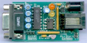
The project designed in the tutorial is an RS232 to RS485 converter. This is a often needed device which can demonstrate a lot of principles of circuit design, and will be useful for some applications as a finished unit. Without meaning to confuse the issue, there is also have available a second, more up-to-date 232-to-485 converter. To see just the example version of the RS485 converter without the tutorial, click here.
RS232 to RS485 Converter specification
|
Select one of the Links below to go to the RS485 converter or the tutorial.